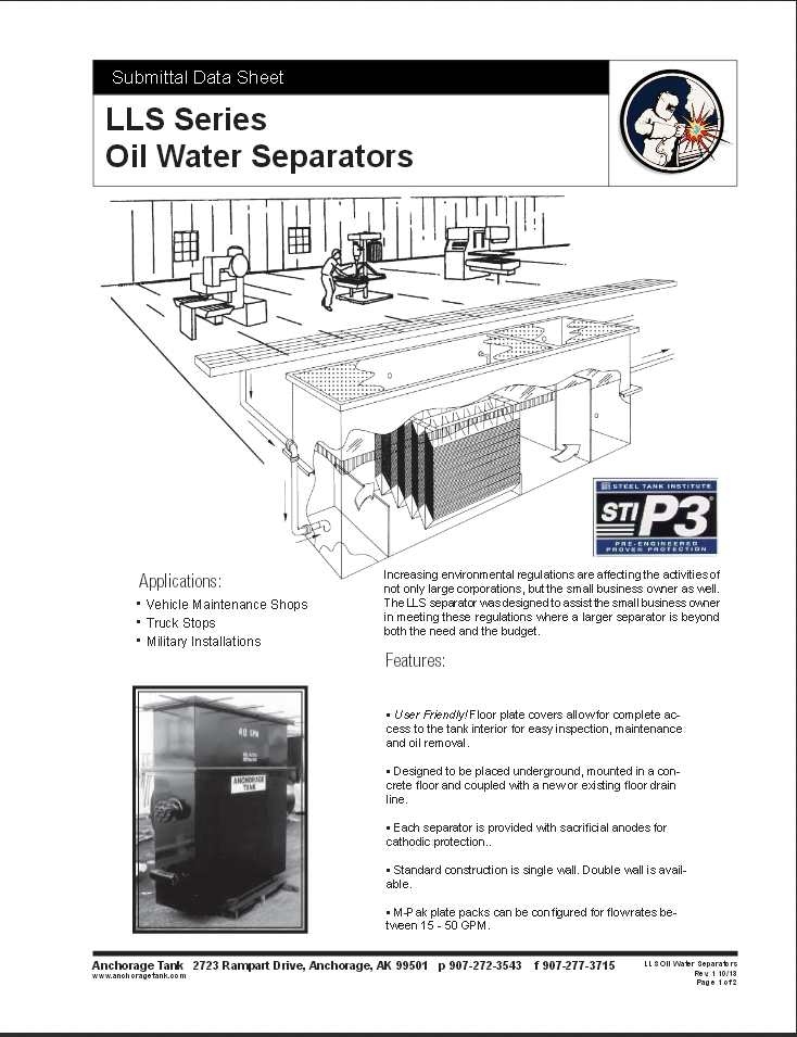
Increasing environmental regulations are affecting the activities of not only large corporations but the small business owner as well. The LLS separator was designed to assist the small business owner in meeting these regulations where a larger separator is beyond both the need and the budget.

Applications:

  • Vehicle Maintenance Shops
  • Truck Stops
  • Military Installations

Features:

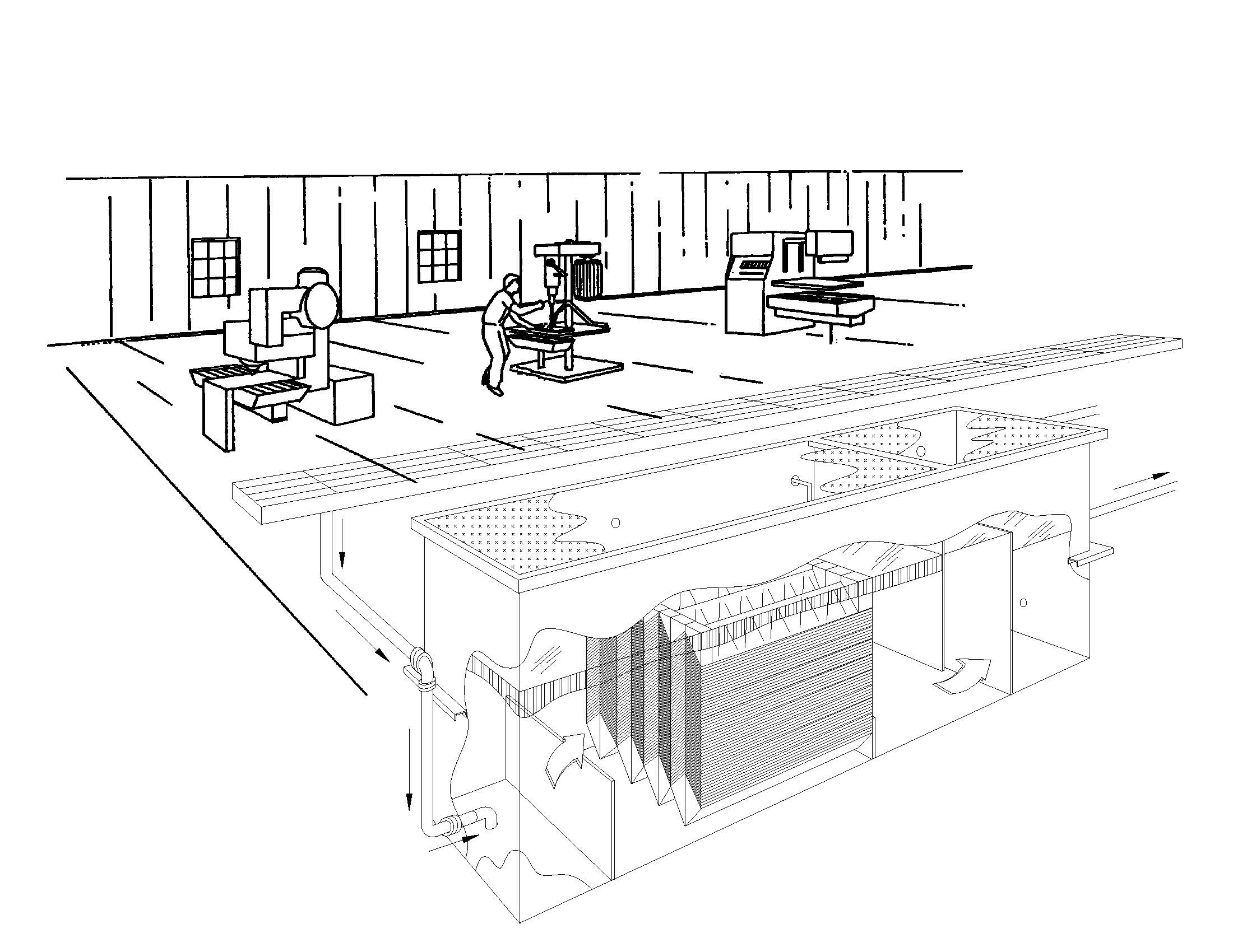
  • User Friendly! Floor plate covers allow for complete access to the tank interior for easy inspection, maintenance, and oil removal.
  • Designed to be placed underground, mounted in a concrete floor, and coupled with a new or existing floor drain line.
  • Each separator is provided with sacrificial anodes for cathodic protection.
  • Standard construction is single wall. Double wall is available.
  • MPak® plate packs can be configured for flow rates between 15 – 50 GPM.

Click image to enlarge

Details

Anchorage Tank Model Number Flow Rate (GPM) Oil Holding Capacity Gallons Tank Length (inches) Tank Width (inches) Tank Height (inches) Inlet / Outlet Diameter (inches) Plate Pack Frontal Area (sq.ft.)
ATLLS-P3-15 15 38 84 25 72 4 3.0
ATLLS-P3-20 20 38 84 25 84 4 3.66
ATLLS-P3-25 25 53 108 25 72 4 2.33
ATLLS-P3-30 30 53 108 25 72 4 3.00
ATLLS-P3-40 40 53 108 25 84 4 4.0
ATLLS-P3-50 50 53 108 25 84 4 4.66

Download O&M Manual

Installation, Operation & Maintenance Manual for LLS STI-P3 Separator.

~ PDF

Download Product Data Sheet

LLS STI-P3 Below Ground Oil Water Separators

~ PDF

Model ATLLS Specification

Provide and install ______ Anchorage Tank Model ATLLS-___ MPak® plate pack gravity displacement Oil Water Separator(s). Separator(s) shall be ______in length, ______ in width, and _____ in height.

Application

The separator shall be designed for gravity separation of free oils (hydrocarbons and other petroleum products) along with some settleable solids from water. The source of the influent to the separator shall be gravity flow from floor drains and spills.

Performance:

Influent Characteristics

Provide Oil Water Separator designed for intermittent and variable flows of water, oil, or any combination of non-emulsified oil/water mixtures ranging from zero to ______gpm. Operating temperatures of the influent oil in water mixture shall range from 40°F. to 45°F. The specific gravities of the oils at operating temperatures shall range from 0.68 to 0.95 and the petroleum hydrocarbon concentration less than or equal to 500 mg/l. The specific gravity of the fresh water at operating temperatures shall range from 1.00 to 1.03.

Effluent Characteristics

The free oil and grease concentration in the effluent from the oil water separator shall not exceed 10 mg/l (10 ppm). Proof shall be provided by the manufacturer in the form of effluent calculations that this goal will be met under the operating conditions specified.

Design Criteria

The oil water separator shall be designed in accordance with Stokes Law and the American Petroleum Institute Manual on Disposal of Refinery Wastes.

Submittals

Provide shop drawings for the oil water separator that show principal dimensions, materials, and locations of all fittings.

Verification

By computer prediction or design calculations, show that the oil water separator is in compliance with effluent requirements when operating under detailed influent conditions. Calculations should show rise and impingement rate at specified specific gravities, water temperature, and oil droplet rise.

Operating Instructions

Provide ______complete sets of installation, operating, and maintenance instructions for the oil water separator system that contain clear and concise descriptions of installation, operation, and maintenance procedures and a list of parts for equipment and data necessary to ordering replacement parts.

Requirements

Provide a shop-fabricated oil water separator system which is comprised of a tank containing an inlet compartment, an oleophilic polypropylene oil coalescing plate compartment, and an outlet compartment.

Inlet Compartment

The inlet compartment shall reduce suspended solids to non-clogging levels for plate packs and provide a uniform oily wastewater loading across inlet face of the oil coalescing compartment under laminar flow conditions. Equip the compartment with an inlet nozzle with a non-clogging flow distributor and energy dissipater device.

Coalescing Compartment

The inlet compartment shall reduce suspended solids to non-clogging levels for plate packs and provide a uniform oily wastewater loading across inlet face of the oil coalescing compartment under laminar flow conditions. Equip the compartment with an inlet nozzle with a non-clogging flow distributor and energy dissipater device.

Outlet Compartment

The outlet compartment shall contain an outlet nozzle equal in size to the inlet nozzle and shall contain a sampling port accessible from the surface.

Fabrication

The separator shall be of _____single wall_____double wall construction. Gasketed floor plate access panels shall extend the entire length of the separator, allowing complete accessibility to all compartments.

Waste Oil Storage

The waste oil storage system shall be an integral part of the proposed oil water separator system. The separated waste oil shall be contained in the upper 30% of the overall tank volume and shall, as it accumulates, displace the normal water level. The waste oil shall reach a predetermined volume, at which time the oil level sensor will indicate that the waste oil level has reached pump-out level. Waste oil may be suctioned by removing the floor plate cover at the surface.

Cathodic Protection

The separator shall be a _____single wall _____double wall underground tank including sacrificial zinc & magnesium anodes.

Automatic High-Level Alarm and Interstitial Leak Sensor

A dual station liquid level sensor for the waste oil level and interstitial leak sensor (in double wall configurations)with a weatherproof NEMA 4 enclosure, enabling indoor or outdoor installation, shall be provided. The system shall automatically activate an alarm device after the waste oil reaches a predetermined level. The system shall be an Anchorage Tank Monitor II Alarm consisting of the control unit and two Tank Assembly Units, probes (lengths as required), or approved equal.

Miscellaneous Appurtenances

Bolts, stiffeners, washers, nuts, screws, pins, and fittings required shall be corrosion resistant which is defined as materials that are nonferrous or nonmetallic. No bolted seams shall be submerged in oily water.

Flanges

Flanges shall be ASTM A105, CI 150, RF, or FF (to match valve and fitting faces), with standard bolt circle, and weld neck type per ANSI B16.5.

Rebar Isolation

Rebar shall be attached to the perimeter of the floor plate access panel frame. To maintain dielectric isolation, this rebar shall never come in direct contact with other rebar or welded wire mesh in a concrete slab.

Lifting Lugs

Fit tank with lifting lugs for handling and installation. Each lug shall carry the total dry weight of the tank and attendant appurtenances.

Vents

Provide a vent for each separator compartment, inlet and outlet pipes, and locate on the separator wall above the oil/water level.

Accessibility

Parts requiring adjustment, cleaning, inspection, or repair shall be accessible and capable of convenient removal when required. Plate Packs shall be fully accessible from the surface.

Quality Control and Tests:

Field Quality Control

The separator shall be installed in accordance with the Steel Tank Institute
Installation Instructions.